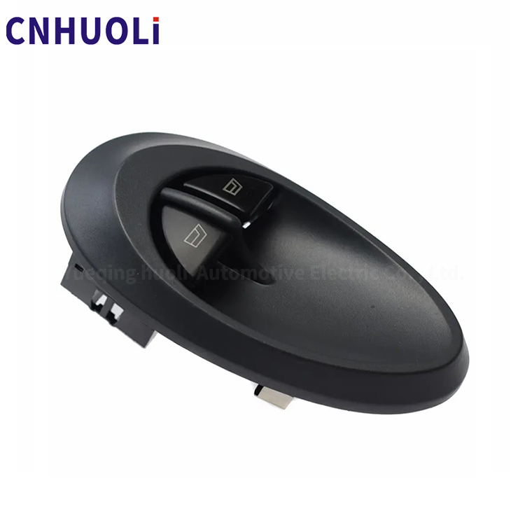
分类
Blog

Enhance Your Driving Experience with Power Window Switches: A Must-Have Feature

When seeking power window switches for an OE (Original Equipment) factory or for original equipment manufacturing purposes, it’s important to consider several factors to ensure the highest quality and compatibility. OE factories typically produce components that meet the specifications of vehicle manufacturers. Here are key considerations:


Partnership with Automotive OEMs:
  • Look for OE factories that have established partnerships with reputable automotive OEMs (Original Equipment Manufacturers).


Quality and Certification:
  • Ensure that the OE factory adheres to rigorous quality standards and holds relevant certifications such as ISO/TS 16949, an automotive industry quality management standard.


Testing Protocols:
  • Confirm that the factory conducts comprehensive testing on their power window switches, including functionality, durability, and safety tests.


Compatibility:
  • Verify that the power window switches produced by the OE factory are designed to be compatible with a wide range of vehicles, meeting the specifications of different car models.


Innovation and Technology:
  • Consider an OE factory that embraces innovation and incorporates advanced technology into their power window switch designs, ensuring a modern and reliable product.


Customization for OEMs:
  • Check if the OE factory can provide customization options to meet the specific requirements and design preferences of automotive OEMs.


Supply Chain Management:
  • Assess the OE factory’s ability to manage the supply chain efficiently, ensuring timely production and delivery of components.


Regulatory Compliance:
  • Confirm that the power window switches comply with regional safety and regulatory standards, meeting the specifications of the target markets.


Production Capacity:
  • Evaluate the OE factory’s production capacity to ensure they can meet the volume demands of automotive OEMs.


When selecting an OE factory for power window switches, thorough due diligence and direct communication with the factory are essential. Engaging in discussions about your specific needs, testing protocols, and production processes will help you establish a successful partnership for the production of high-quality OE power window switches.

分类
Blog

Unlocking the Secrets of Power Window Switches: A Comprehensive Overview

Unlocking the secrets of power window switches involves understanding their components, functionality, and the key considerations when choosing a reliable China automobile switch supplier. Here’s a comprehensive overview to guide you through this process:


Components of Power Window Switches:

a. Switch Mechanism: The core of the power window switch, determining its functionality.

b. Circuitry: Wiring and electronic components ensuring smooth operation.

c. Buttons: Controls for individual windows, door locks, and mirror adjustments.

d. Illumination: LED or backlighting for visibility in low-light conditions.

e. Connectors: Interfaces with the vehicle’s electrical system.


Functionality:

a. Single vs. Master Switch: Single controls one window; master controls all.

b. Auto-Up/Down: Allows one-touch operation for convenience.

c. Lockout Feature: Disables other window controls, ideal for child safety.

d. Mirror Adjustment: Integrated controls for side mirror adjustments.

e. Compatibility: Ensure compatibility with various vehicle models.


Quality Standards:

a. ISO Certification: Look for suppliers with ISO 9001 or 14001 certification.

b. Testing Protocols: Ensure switches undergo rigorous testing for durability and performance.

c. Material Quality: High-grade materials for longevity and reliability.

d. Water and Dust Resistance: Essential for switches exposed to the elements.


Customization Options:

a. Design Flexibility: Ability to customize switch aesthetics.

b. Logo Branding: Option to include your brand logo on the switches.

c. Backlight Colors: Choose backlighting that aligns with your brand or vehicle design.


Supplier Selection:

a. Reputation: Research and choose suppliers with a positive track record.

b. Production Capacity: Ensure the supplier can meet your quantity demands.

c. Quality Control: Confirm the presence of a robust quality control process.

d. Communication: Clear and prompt communication is crucial for a smooth partnership.


Cost Considerations:

a. Unit Price: Negotiate competitive unit prices.

b. MOQ (Minimum Order Quantity): Ensure MOQ aligns with your business needs.

c. Shipping Costs: Consider shipping costs, especially for bulk orders.


After-Sales Support:

a. Warranty: Check the warranty period and terms.

b. Customer Service: Evaluate the supplier’s responsiveness to inquiries and concerns.


Legal and Compliance:

a. Regulatory Compliance: Confirm adherence to regional safety and quality standards.

b. Contracts: Have clear contracts outlining terms, conditions, and responsibilities.


By thoroughly understanding these aspects, you’ll be better equipped to unlock the secrets of power window switches and find a reliable China Car Switches Factory for your business. Always prioritize quality, reliability, and clear communication in your supplier relationship.

分类
Blog

The Ultimate Guide to Understanding and Fixing Your Power Window Switch

Understanding and fixing power window switch issues from a manufacturing perspective involves ensuring the production of high-quality switches and addressing potential problems. Here’s a guide tailored to the context of a China window switches factory:


Quality Control in Manufacturing:
  • Robust Materials: Ensure that the power window switches are made from durable and high-quality materials, considering factors like wear resistance and electrical conductivity.
  • Precision Manufacturing: Use advanced manufacturing processes to create switches with accurate dimensions, ensuring a perfect fit in various car models.


Testing Procedures:
  • Functionality Testing: Implement stringent testing procedures to ensure the functionality of each switch. This includes testing individual buttons for responsiveness and the overall reliability of the switch.
  • Durability Testing: Subject switches to durability tests, simulating prolonged use to identify potential weaknesses and improve overall lifespan.


Wiring and Electrical Components:
  • Secure Connections: Ensure that wiring connections within the switch are secure and properly insulated to prevent electrical issues.
  • Resistant to Environmental Factors: Design switches to withstand various environmental factors, such as temperature variations and humidity, to ensure longevity.


Supplier Quality Control:
  • Vetted Suppliers: Establish relationships with reliable suppliers for raw materials and components. Conduct regular quality checks on incoming materials to maintain consistent quality.
  • Traceability: Implement traceability measures to identify and rectify issues in the supply chain promptly.


Assembly Process:
  • Efficient Assembly Lines: Optimize the assembly process to ensure efficiency and minimize the risk of defects.
  • Employee Training: Train assembly line workers on the importance of precision and quality control at every stage of production.


Addressing Common Manufacturing Issues:
  • Faulty Contacts: Develop procedures to identify and rectify faulty contacts during manufacturing. Implement automated systems for contact testing.
  • Inadequate Lubrication: Ensure that moving parts are adequately lubricated during the assembly process to prevent issues like button sticking.


Continuous Improvement:
  • Feedback Loops: Establish a feedback loop between the production line and quality control to continuously improve the manufacturing process.
  • Technology Integration: Embrace technological advancements, such as automated inspection systems, to enhance quality control measures.


Customer Feedback and Warranty Claims:
  • Customer Support Team: Establish a responsive customer support team to handle inquiries and warranty claims efficiently.
  • Root Cause Analysis: Conduct thorough investigations into warranty claims to identify root causes and implement corrective actions.


Compliance with Standards:
  • Adherence to Standards: Ensure that the manufacturing process complies with industry standards and regulations to meet safety and quality requirements.
  • Certifications: Obtain relevant certifications to demonstrate commitment to product quality and safety.


Sustainability Practices:
  • Environmentally Friendly Materials: Consider using environmentally friendly materials and processes in line with global sustainability initiatives.
  • Recycling Programs: Implement recycling programs for waste generated during the manufacturing process.


By focusing on these aspects, an automobile switch supplier involved in power window switch manufacturing can produce high-quality products, reduce defects, and contribute to overall customer satisfaction and safety. Continuous improvement and adherence to industry standards are key elements in building a reputable and successful manufacturing operation.

分类
Blog

The Ultimate Guide to Choosing the Perfect Power Window Switch for Your Car

Choosing the perfect power window switch for your car involves considering several factors to ensure compatibility, functionality, and aesthetics. Here’s a comprehensive guide to help you make an informed decision:


Compatibility:
  • Make and Model: Ensure the power window switch is compatible with your car’s make and model. Different cars may have varying wiring and switch configurations.
  • Year of Manufacture: Some switches are designed for specific model years, so verify that the switch matches your car’s production year.


Type of Switch:
  • Single or Master Switch: Decide whether you need a single switch for individual windows or a master switch that controls all windows.
  • Illuminated or Non-Illuminated: Illuminated switches are easier to locate in the dark but may affect the overall aesthetic. Choose based on your preference.


Design and Aesthetics:
  • OEM vs. Aftermarket: Original Equipment Manufacturer (OEM) switches are designed for your specific vehicle, providing a seamless look. Aftermarket switches may offer more features and styles but might not match your car’s interior perfectly.
  • Color and Finish: Choose a switch that complements your car’s interior. Consider factors like color, texture, and finish.


Functionality:
  • Auto-Up and Auto-Down Features: Some switches offer one-touch auto-up and auto-down functions for convenience. Check if your vehicle supports these features.
  • Lockout Feature: A lockout switch prevents passengers from operating their own windows, enhancing safety, especially for rear-seat passengers.


Installation:
  • Plug-and-Play vs. Wiring Modification: Opt for a switch that is easy to install. Some switches are designed as plug-and-play, while others may require wiring modifications.


Durability and Quality:
  • Material: High-quality materials ensure durability. Look for switches made from robust materials that can withstand frequent use.
  • Brand Reputation: Choose switches from reputable brands with positive reviews to ensure reliability.


Warranty and Support:
  • Warranty Period: Check the warranty offered by the manufacturer. A longer warranty period indicates confidence in the product’s quality.
  • Customer Support: Choose a brand that offers good customer support in case you encounter any issues during installation or use.


Budget:
  • Cost Consideration: Set a budget and look for a power window switch that meets your requirements within that budget. Be wary of overly cheap options, as they may compromise on quality.


Reviews and Recommendations:
  • Customer Reviews: Read reviews from other car window switch manufacturers to get insights into the performance and durability of the switch you’re considering.
  • Recommendations: Consult with auto professionals or seek recommendations from car enthusiasts for trusted brands and models.


By carefully considering these factors, you can confidently choose the perfect power window switch for your car, ensuring a smooth and reliable window control experience.

分类
Blog

What are the types of car sensors

There are different sensors on the vehicle, and they play different roles. Car owners want to further understand the sensors on the vehicle, so what are the types of car sensors?

1. Throttle position sensor: The throttle position sensor is usually located on the throttle of a vehicle, and its main function is to detect the opening and closing of the throttle.

2. Intake pressure sensor: It can detect the pressure in the intake manifold based on the engine load, convert it into a signal and send it to the trip computer as a reference for determining the fuel injection volume of the vehicle.

3. Crankshaft position sensor: The main function is to check the vehicle’s crankshaft angle signal, engine speed signal, and dead center signal. The above signals are transmitted to the driving computer, and the engine will calculate the optimal ignition time.

4. Air flow sensor: It converts the inhaled air into an electrical signal and sends it to the vehicle’s on-board computer to determine the fuel injection status of the vehicle.

5. Oxygen sensor: divided into front oxygen sensor and rear oxygen sensor. The front oxygen sensor checks the oxygen content after combustion of the mixture, while the rear oxygen sensor checks the oxygen content after purification of the three-way catalytic converter.

分类
Blog

How to choose a car relay

Relay is an electrical control device commonly used in automation control circuits, playing a role in automatic regulation, safety protection, conversion circuits, etc. It is actually an “automatic switch” that uses small current to control high current operation.

1. Determine relay types based on different input signals

There is no problem selecting electromagnetic, temperature, time, or photoelectric relays based on whether the input signals are electrical, temperature, time, or optical signals. The selection of voltage and current relays is specifically explained here. If the relay coil supplied by the entire machine has a constant current, a current relay should be selected, and if it has a constant voltage value, a voltage relay should be selected.

2. Selection of input parameters

The input quantity closely related to the user is the coil working voltage (or current), while the pull-in voltage (or current) is a parameter that the relay manufacturer controls, judges, and evaluates the sensitivity of the relay. For users, it is just a working limit parameter value. The control Factor of safety is the working voltage (current)/pull in voltage (current). If the relay is used at the pull in value, it is unreliable and unsafe. When the ambient temperature rises or the relay is under vibration and shock conditions, the relay will not work reliably.

When designing the entire machine, the no-load voltage cannot be used as the basis for the working voltage of the relay, but the actual voltage should be calculated by connecting the coil to the load, especially when the internal resistance of the power supply is high. When using a transistor as a switching element to control the coil on/off, the transistor must be in the on/off state. For relays with operating voltages below 6VDC, the saturation voltage drop of the transistor should also be deducted. Of course, the higher the working value, the better. Exceeding the rated working value too high will increase the impact wear of the armature, increase the number of contact bounce, and shorten the electrical life.

3. Select according to the usage environment

The environmental conditions for use mainly refer to temperature (maximum and minimum), humidity (generally the maximum relative humidity at 40 ℃), Low-pressure area (not considered below 1000 meters), vibration and shock. In addition, there are requirements for packaging methods, installation methods, external dimensions, and insulation. Due to different materials and structures, the environmental mechanical conditions that the relay can withstand vary. If used beyond the environmental mechanical conditions specified in the product standard, it may damage the relay. Therefore, the relay can be selected according to the environmental mechanical conditions of the entire machine or higher level conditions.

It is best not to use AC powered relays around devices that are sensitive to electromagnetic or radio frequency interference. When selecting DC relays, products with coil transient suppression circuits should be selected. For areas where solid-state devices or circuits are used to provide excitation and are sensitive to peak signals, products with transient suppression circuits should also be selected.

4. Select the type and capacity of relay contacts based on load conditions

It is important to determine parameters based on the size of the load capacity and the nature of the load (resistance, inductance, capacitance, lamp load, and motor load). It is incorrect to believe that a small switching load on a contact is necessarily more reliable than a large switching load. Generally speaking, relay switching is negative

分类
Blog

Solid State Relay

Introduction

Relays play a significant role in electrical control systems. There are many types of relays like electromagnetic relays, time relays and thermal relays. Solid state relays (SSRs) are one of them. They can supply/cut-off power to electrical appliances using a low voltage control signal. In this article, we’ll be discussing SSRs, how they work and their applications.

Introduction To Relay Types

There are times where we need to control a high voltage/high current electrical equipment using a small signal. For example, imagine a scenario where we need to control a 220V single phase 1HP motor using a small switch/button or using a PLC. In an application like this, the motor cannot be connected directly to the PLC or the switch. This not only exceeds the switch’s rating, but also poses an electrical hazard due to high voltages and current being handled.

Relays are useful in such instances. A relay allows us to control a large appliance which draws higher current (such as a 220V 20A load) using a small voltage signal (24V, 100mA). A relay also provides electrical isolation between the high voltage side and the low voltage side. Relays are on/off type devices that have only those two distinct modes of operation.

Before we move onto solid-state relays, let’s go through some of the most popular types of relays available in the market to understand how a regular relay works.

There are many types of relays available in the market. In general, they are electrically controlled on/off switches that have single/multi-pole and throw setup.

Here are some of the popular relay types and their functionality in brief:

  • Electromagnetic/Electromechanical relays
    • These are the most popular and generic types of relays. They consist of a mechanical arm that makes/breaks contact with the contact conductive terminals of the relay, and it is actuated by applying a voltage to the built-in coil. Electromagnetic relays can control both AC and DC appliances. Electromagnetic relays are available in various coil voltages and contact ratings.
  • Small signal relays
    • Small signal relays are mostly found in automotive and industrial automation applications. These are miniature versions of electromechanical relays that switch low voltage, low current signals such as PLC digital output signals.
  • Time-delay relays
    • Time delay relays consist of a built-in timer and an electromechanical relay to delay turning on after applying a turn-on signal. These are found in motor control circuits to start high power motors.
  • Polarized relays
    • Polarized relays are a special type of relay that are sensitive to the direction of current applied. When a DC current is applied to the coil in a certain polarity, the relay switches to a certain position, activating a certain set of contacts. When the polarity is swapped, it activates another set of contacts. When power is removed, some polarized relays return to a ‘neutral position’ to break all contacts.

The other most popular relay type is the Solid State Relay. With the understanding about the relays we’ve got so far, let’s discuss solid state relays.

What Is A Solid State Relay?

A Solid state Relay (also known as SSR) is another type of relay that operates from a small AC/DC input signal. SSRs work very similarly to EMRs (Electro-Meahcnical Relays). However, they do not have the moving components. SSRs instead use electrical and optical components (which gives the name solid-state) to perform the switching task and keep the input signal isolated from the switching side.

Similar to an electromechanical relay, solid-state relays also provide near-infinite contact resistance/impedance when open and near-zero resistance/impedance during operation. Depending on the internal construction of the control circuitry, SSRs can control either AC, DC or both types. This is possible due to the variety of semiconductor choices available as the power electronics. Solid-state relays can be designed using SCRs, TRIACs or even transistors/MOSFETs.

One of the key things that differentiates a SSR with its electromechanical counterpart is the operational life. Electromechanical relays have a very limited contact lifecycle because they physically engage/disengage the contacts. This causes electrical arcs to generate between the opening contacts which degrades the contact surface. While the heavy duty relays are designed to counter this, they are not permanently immune to the wear and tear.

SSRs, on the other hand, are fully solid state and have zero moving parts. This allows them to last thousands of switching cycles under rated load without having to worry about the operational stability. This also improves the switching speed of the SSR.

Solid State Relay Circuit

Solid state relays are simple devices from a usability point of view. They have control signal input, and a switched output that controls high power electrical loads. Their internal construction is far more complicated that what meets the eye. Let’s discuss the SSR circuit and how it works.

As mentioned before, solid state relays offer electrical isolation between the control signal side and the load side. Similar to electromechanical relays where the isolation happens through physically separated contacts, SSRs achieve this by optically isolating the input signal.

This is done using a special semiconductor device called ‘optocoupler’ (also known as ‘optoisolator’.). Optocouplers contain one or more infra-red emitting diodes or LEDs along with a photosensitive device to provide optical signal isolation.

When the control signal is provided (very low DC voltage in the range of 2-3V), it turns on the IR LED built-in to the SSR. The emitted beam is received by the photosensitive device to activate the output. The photosensitive device is placed farther from the emitter and to provide the electrical isolation. With this implementation, an SSR can easily switch a 220V AC load with a control signal as low as 5V DC.

The control signal can originate multiple ways. It can be either,

  • Solid state DC signal
    • Solid state DC signals can be originating from simple switches or direct power sources like battery cells.
  • Digital output signal
    • Controllers such as microcontrollers or microprocessors, PLCs can also generate signals that can be fed into SSRs for controlling loads.
  • Logic gate signals
    • For applications that do not require the processing power of a microcontroller, a combinational logic gate circuit’s output can be connected to an SSR for turning a load on/off according to a set of conditional inputs.

Types Of SSRs

There are many types of solid-state relays. They differ from each other by the functionality. The operating principle is very similar, although they are used in different applications.

Instant Switching SSR

Instant switching solid-state relays switch the output on immediately when a control voltage is applied. These SSRs have atypical response time less than 1 milliseconds, making them an ideal component for applications that require fast response and/or phase angle control. These also find applications in inductive load switching.

Instant switching SSRs are usually made of triacs to allow the control of AC signals regardless of the phase angle at the moment of switching. This works identical to a regular switch where the turn on point is random.

Zero Switching SSR

Zero switching, also known as zero-crossing SSRs, turn on at the first zero crossing point of the line voltage regardless of the time control signal is applied. For a 50Hz sinusoidal line voltage, the response time can be between near-zero to 10ms (less than half period).

These SSRs have a special built-in circuitry called ‘zero crossing detector’. When the control signal is applied, this circuit generates a pulse as soon as the AC sinusoidal waveform reaches 0V point. This turns on the triac that controls the load and the triac stays conductive until the line voltage reaches zero again. The cycle repeats as long as the control voltage is applied.

Zero crossing SSRs find their applications in resistive, capacitive and inductive load control systems. The activation at zero-crossing point ensures a minimum surge current flowing into the load during startup.

Peak Switching SSR

Complementary to the zero-crossing type, peak switching SSRs activate the output at the first peak of the line voltage upon applying the control voltage. After this half-cycle, the SSR continues to function like a zero-crossing SSR.

In peak switching SSRs, a zero-crossing detector is coupled with an initial peak detector stage to generate the first turn-on pulse. The SSR does not turn on until the line voltage reaches its peak voltage. As soon as the peak is detected, the load receives power through the triac. When switched at a peak of the supply voltage, inductive loads draw the least amount of inrush current. The use of peak switching SSRs is beneficial in such applications to ensure the load is protected from inrush currents.

Peak switching SSRs are used with heavily inductive loads such as transformers and high power motors.

Analog Switching SSR

Analog switching SSR are a special type of SSRs. They operate with a 4-20mA DC current signal. The output’s phase is proportionally influenced by the input signal. When the control voltage/current signal is removed, the SSR turns off. Analog solid state relays have built-in circuitry that functions as a closed-loop feedback system to control the output voltage as a function of the input voltage.

DC Switching SSR

For resistive and inductive loads, DC switching SSRs are widely used. DC SSRs control the load using MOSFETs of BJTs therefore they are best used with DC loads such as DC heating elements, solenoid valves and DC brushed motors. Since these do not have built-in inductive kickback protection, an external freewheeling diode is required to be connected to the output terminals in reverse bias configuration.

Control Methods

Different types of SSRs have different driving methods. As mentioned above, SSRs require only a small control signal to switch a higher voltage, higher current load. Here are some of the methods used to drive a SSR’s input.

Direct DC Switching

The simplest method of driving an SSR is by applying the control voltage directly to the SSR. For example, if an SSR’s control voltage is 12V DC, directly supplying the voltage signal to the control inputs turns on the SSR. This type of simple implementation can be found in direct-on-line motor control circuits.

Transistor Control

In some cases, the control signal voltage may not be high enough to directly drive the SSR’s inputs. For instance, a microcontroller running at 5V or 3.3V may not be able to provide enough voltage and current to drive the SSR’s internal circuitry. In such cases, the logic voltages need to be translated to a control signal to the SSR’s input. By implementing a circuit similar to the above image, a small input signal can easily control the SSR. The NPN transistor circuit shown above can turn on the SSR when a positive voltage is applied to the base terminal.

Combinational Logic Control

In applications where conditional logic is needed, yet the system is too simple to be controlled by a microcontroller based control system such as a PLC, logic gates can be used. With a circuit similar to the one shown below, the inverted output of a positive combinational logic circuit can directly drive a SSR to control an electrical load.

AC Control Signal

Some systems use only AC power in both control and power electronics. Incorporating an SSR into such a system can be challenging because SSRs are mostly driven using DC signals. However, with the principle of full-bridge rectification, an AC signal at a compatible voltage level can be converted into a rectified DC voltage signal to drive the SSR’s inputs. The figure below shows such an implementation.

However, most of the SSR manufacturers offer AC input solid state relays in their SSR series to overcome this added overhead.

Solid State Relay Advantages

SSRs have many advantages including,

  • Long life and high reliability
  • Fast response times
  • Low EMI
  • No contact arcing due to lack of mechanical components
  • High resistance to vibration, shock and dust
  • Silent operation
  • Logic compatibility

However, SSRs have a few disadvantages too:

  • Contact voltage drop
    • Since SSRs are made using semiconductor devices, they pose an inherent series resistance even when fully turned on. For example, thyristors can have a voltage drop of 1-1.6V across the terminals. This generates heat, which requires passive or active cooling.
  • Transient voltage problems and dV/dt limitations
    • If not implemented properly, SSRs pose the risk of random turn-on caused by regenerative action due to the inherent capacitance present in the semiconductor stages.

How To Choose Right Solid State Relay

When choosing a SSR for a particular application, consider the following key points:

General information

Select a SSR that can handle the rated load current, voltage and the operating temperature. The SSR should generally have a higher rating than the intended application.

Protection features

The SSR should have adequate protection from thermal overload, over-current and transient voltage protection. In many cases, such circuitry should be connected externally.

Also, ensure that the SSR complies with the insulation standards for the application. For example, higher end SSRs have input-to-output insulation resistance of >=4000Vrms AC and output to case insulation resistance of >= 2500Vrms AC

Compliance to industry standards

Selecting an SSR that’s been manufactured to conform with IEC, UL and similar industry standards will ensure the system integrity and reliability.

Conclusion

Solid state relays are excellent switching devices that can replace conventional electromechanical relays in many cases. The initial cost of implementing an SSR based system is relatively high, the advantages easily outweighs the disadvantages and justifies the cost.

Home
WhatsApp
EMail
Go Top